- Case IH Warning Lights & Dash Symbols
- Case IH Farmall Series Warning Lights
- Case IH Maxxum Series Warning Lights
- Case IH Puma Series Warning Lights
- Steiger & Magnum Series Warning Lights
- All Case IH Tractor Dash Symbols & Lights
- General Symbols
- Electric-related Dash Symbols
- Engine-related Dash Symbols
- Body-related Dash Symbols
- PTO-related Dash Symbols
- Hydraulic-related Dash Symbols
- Loader-related Dash Symbols
- Colors of Case IH Tractor Warning Lights
- How to Reset Case IH Warning Lights?
The Case IH dashboard symbols, warning lights, indicators, and gauges serve several important functions to help prevent equipment accidents. They alert the operator to potential issues or malfunctions with the tractor’s critical systems, such as: exhaust filter clogging, engine and transmission malfunctions, charging system issues. The warning lights prompt the operator to take immediate action, such as cleaning or replacing the air filter, checking oil levels, shutting off the engine if a serious malfunction occurs and reviewing error messages.
The Case IH dash indicators provide real-time information to the operator about the tractor’s operating status, such as PTO engagement, differential lock status, trailer/vehicle turn signal activation. The Case IH information display provides diagnostic data and trouble codes, allowing the operator to quickly identify and address problems before they escalate.
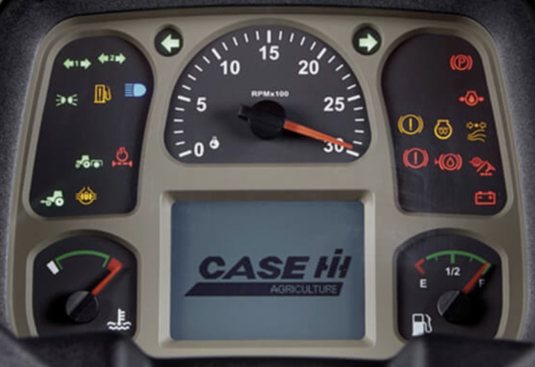
Case IH Warning Lights & Dash Symbols
By alerting the operator to issues and providing critical operating information, the Case IH dashboard symbols, warning lights, and indicators help the operator maintain control of the tractor and prevent accidents that could result from equipment malfunctions or operator errors. Promptly addressing warning lights and indicators is crucial for safe and efficient tractor operation.
Case IH Farmall Series Warning Lights
As you navigate your Case IH Farmall series tractor through the rigors of agricultural work, understanding these warning lights is paramount.
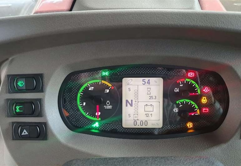
They serve as your vehicle’s voice, alerting you to potential issues before they escalate, ensuring uninterrupted productivity on the farm.
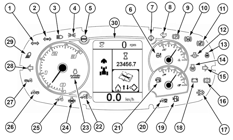
- Trailer’s 1 Turn Signal Indicator (green)
- Trailer’s 2 Turn Signal Indicator (green)
- High Beam (blue)
- Parking Light (green)
- Stop Light (red)
- Engine Coolant Temperature Gauge
- Master System Warning Indicator Light (orange)
- High-Speed Mode Indicator (green)
- Parking Brake Warning Light (red)
- Trailer Brake Pressure Warning Light (red)
- Brake Pedal Warning Light Not Connected (red)
- Engine Oil Pressure Indicator (red)
- Engine Power (% kW)
- Low Temperature Engine Start Aid (orange)
- Right Turn Signal Indicator (green)
- Brake Failure / Malfunction
- Clogged Filter (DEF) Warning Light (green)
- Alternator Charging Indicator (red)
- Fuel Level Warning LIght (orange)
- PTO Rear Indicator
- Fuel Level Gauge
- Automatically Engaged Four-Wheel Drive (green)
- Tachometer / Engine Rotational Speed
- Differential Lock (orange)
- Four-wheel Drive Indicator (green)
- Warning Light for Rear PTO (yellow)
- Warning Light for Front PTO (yellow)
- Left Turn Signal Indicator (green)
- Work Light (orange)
- Case IH Information Display
Case IH Maxxum Series Warning Lights
Case IH Maxxum Series tractor warning lights and indicators are essential components of the tractor’s dashboard interface, serving several critical purposes. Warning lights alert operators to potential hazards or malfunctions, allowing them to take corrective action promptly and prevent accidents or injuries. These indicators provide real-time feedback on various systems and components of the Case IH tractor, including engine health, hydraulic pressure, temperature, and fuel levels. Monitoring these parameters helps prevent damage to the tractor and ensures optimal performance.
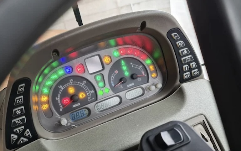
Diagnostic Information: Warning lights can indicate faults or errors within the tractor’s systems, facilitating troubleshooting and maintenance. Identifying issues early can prevent costly repairs and downtime. By providing clear and immediate feedback on the tractor’s status, warning lights enable operators to make informed decisions to optimize efficiency and productivity during agricultural tasks.
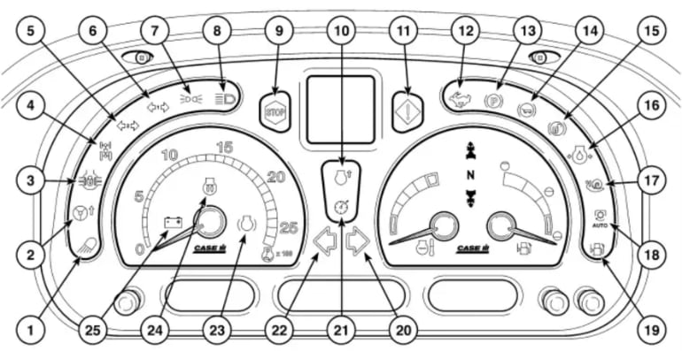
- Work Light – Indicates the status of the work lights on the Case IH tractor.
- Turn Assist – When the inner ring is pressed, the indicator comes on to show when Turn Assist is activated.
- Differential Lock – Display lights up when the differential lock is activated.
- All-wheel Drive – Display lights up when the drive to the front wheels is activated.
- Trailer 2 indicator – Display flashes when the trailer indicators are on, if a second trailer is attached.
- Trailer 1 indicator – Display flashes when the trailer indicators are on, if a first trailer is attached.
- Parking – Display lights up when the tractor lights are switched on.
- Main Beam – Display lights up when the tractor lights are switched to main beam.
- STOP – As soon as this light comes on, stop the tractor and identify the cause. A warning symbol appears on the dot matrix display to confirm the location of the error.
- Power Boost – Activated when this display lights up, the symbol is shown at the same time on the dot matrix display.
- Master System Warning – When this display lights up, a warning symbol is shown at the same time on the dot matrix display. Switch off the tractor and determine the cause.
- High-Speed Mode – Indicates when the tractor is operating in a high-speed mode. This mode may be engaged when the tractor is traveling at higher speeds, such as during road transport or when using certain implements that require increased velocity.
- Parking Brake – Display lights up when the starter switch is pressed and the parking brake is applied. If the starter switch is switched off and the parking brake is not applied or if thedriver leaves his seat without applying the parking brake, a warning buzzer sounds for around 10 seconds until the parking brake is applied.
- Trailer Brake Pressure – When this light flashestogether with a warning buzzer, it means thatthe brake fluid pressure in the trailer brakecircuit is too low. The stop light also lights up.Switch off the tractor and determine the cause.
- Brake Pedals Not Latched – Light comes on to show when pedal latch is unlocked (Japan only).
- Engine Oil Pressure – When this display is continuously lit up in conjunction with the red STOP symbol, it means that the engine oil pressure is too low. Switch off the engine and determine the cause.
- Creeper Gears – Display lights up when the creeper gears are activated.
- Auto PTO Function – Display lights up when the auto PTO function is engaged. The light flashes as soon as the attached equipment is raised with the automatic PTO activated. When the attached equipment is lowered to working position, the display stops flashing and lights up continuously.
- Fuel Level – Display lights up when the Case IH tractor needs more fuel.
- Right Turn Indicator – The indicator flashes alongwith the tractor’s right-hand turn indicator.
- Constant Speed – This indicator comes on when constant speed is activated.
- Left Turn Indicator – The indicator flashes along withthe tractor’s left-hand turn indicator.
- Engine Back Pressure Brake – Display lights upwhen the engine back pressure brake is activated.
- Cold Start Equipment – Display lights up when the auxiliary start system is switched on using the starter switch.
- Alternator – If this indicator lights up permanently when the engine is running, this indicates that the alternator is not charging the battery.
Case IH Puma Series Warning Lights
The instrument cluster provides real-time information about the tractor’s performance, including engine RPM, temperature, fuel level, and hydraulic pressure.
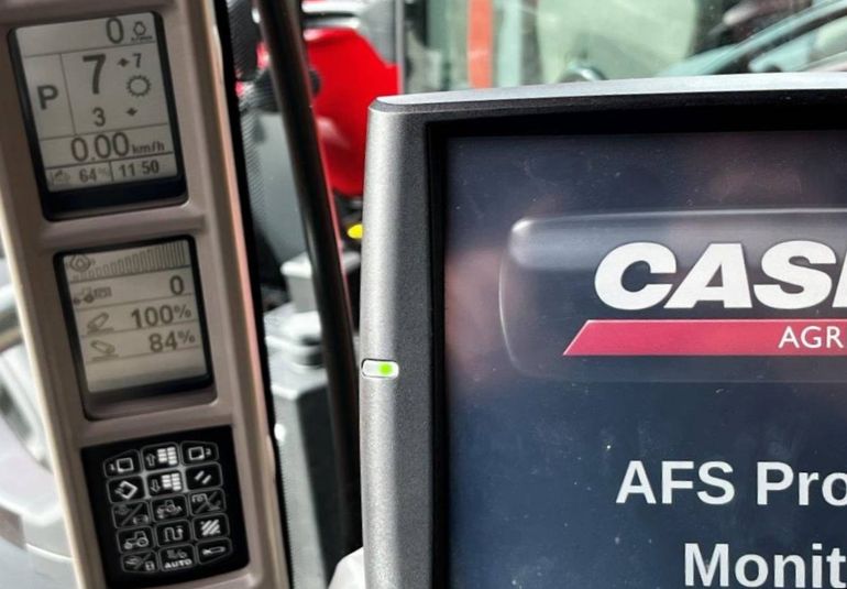
This data allows operators to monitor the tractor’s systems and make necessary adjustments to optimize performance and efficiency.
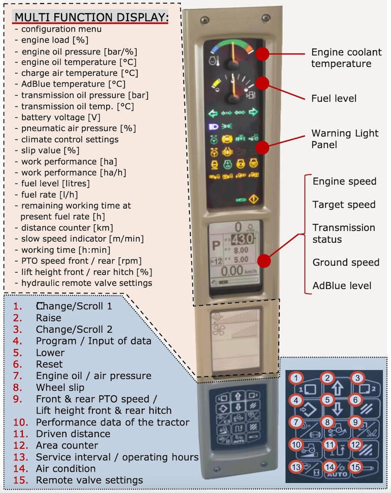
Warning lights serve as diagnostic indicators, signaling when maintenance or repairs are required. By promptly addressing issues indicated by warning lights, operators can prevent minor problems from escalating into major mechanical failures, reducing downtime and repair costs.
Steiger & Magnum Series Warning Lights
The Case IH Steiger & Magnum Series Tractor Instrument Cluster with Warning Lights is an essential component of these high-performance agricultural machines. The instrument cluster provides operators with a comprehensive overview of the tractor’s vital parameters, including engine RPM, temperature, fuel level, hydraulic pressure, and more. This real-time monitoring allows operators to ensure optimal performance and prevent potential issues before they escalate.
Instrument Cluster for CVXDrive™ Case IH Magnum Series Tractors
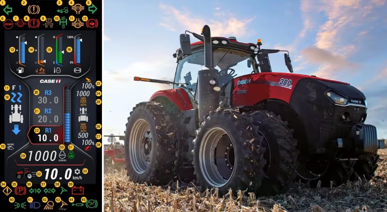
In addition to warning lights, the instrument cluster may feature diagnostic codes or messages, providing valuable insight into the root cause of any issues. This diagnostic capability enables operators to troubleshoot problems more effectively and facilitates faster repairs by service technicians. Having all essential information displayed in one central location enhances operator convenience and efficiency. Operators can quickly glance at the instrument cluster to monitor performance metrics and make informed decisions about tractor operation without distraction.
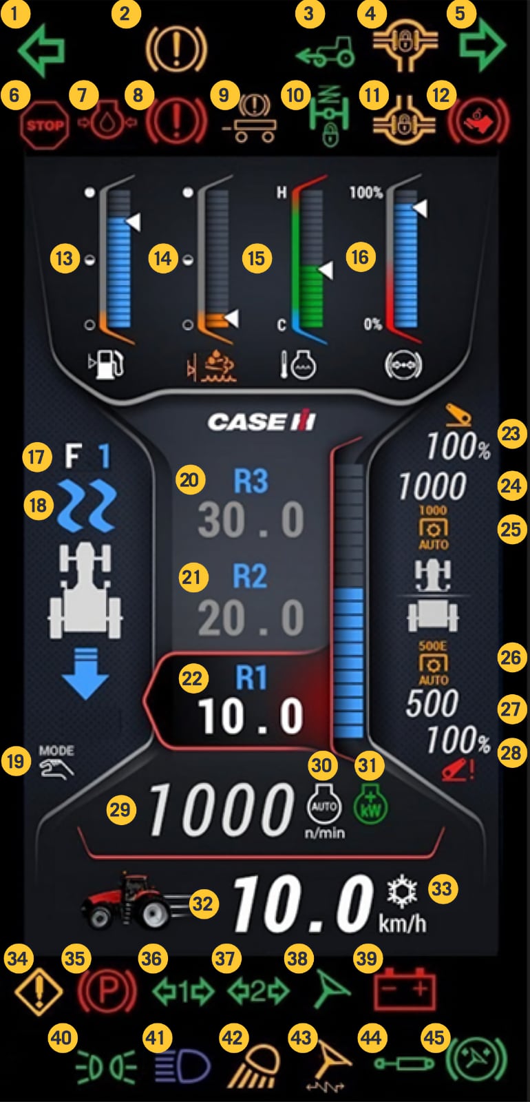
- The left turn signal arrow.
- The brake warning light.
- Tractor’s MFD is engaged – Illuminates when the MFD is engaged, the automatic MFD engages, or when both brake pedals are applied.
- Front Diff-lock is engaged – Illuminates when the Diff-lock is turned on by the operator, the Auto Diff-lock is turned on and the tractor is going in a straight line (N/A on Magnum).
- The right turn signal arrow.
- The STOP warning light – Illuminates when there is a fault that requires immediate attention.
- Low engine oil pressure.
- Not applicable in North America.
- Trailer brakes are active – If equipped, this light will come on when the trailer brakes are active.
- Front axle suspension is locked out – This light will come on when the front suspension system is turned off by the operator, or the tractor is in Park.
- Rear axle Diff-lock is engaged – Illuminates when the Diff-lock is turned on by the operator, the Auto Diff-lock is turned on and the tractor is going in a straight line.
- Not Available in North America.
- Fuel level.
- DEF level.
- Coolant temperature.
- Air pressure, if present – If not, then engine oil pressure (Air pressure shown).
- Tractor Direction – Indicates tractor direction of travel (reverse shown).
- Anti-Jack Knife Feature is shown when activated.
- Transmission mode – AUTO or MANUAL (Manual shown).
- R3 target speed (F3 forward).
- R2 target speed (F2 forward).
- R1 target speed (F1 forward).
- Front Hitch position in percent.
- Front PTO RPM.
- Front PTO engaged.
- Rear PTO engaged.
- Rear PTO speed.
- Rear Hitch position in percent.
- Engine RPM.
- Constant Engine Speed.
- In this location one of the following icons will appear: Engine Power Boost, Engine Compression Brake, or Engine Grid Heater.
- Ground Speed.
- Low temperature warning – for hydraulic oil.
- Yellow Warning Light – Warns operator that a fault exists that needs to be serviced.
- Park break applied light. Illuminates when the tractor is placed in “Park”.
- Not applicable in North America.
- Not applicable in North America.
- Guidance On – Guidance system has control of the tractor’s steering system.
- Battery – Alternator not charging the battery.
- Road Lights On – Road lights are on.
- Bright Lights On – High beam road light are on.
- Work Lights On – Work lights are on.
- Guidance Inactive – Guidance is on but not engaged.
- Hydraulic Valve Activated – Illuminates as long there is flow from at least one remote in either direction.
- Not applicable in North America
Instrument Cluster for PowerDrive Case IH Magnum Series Tractors
Having all essential information displayed in one central location enhances operator convenience and efficiency. Operators can quickly glance at the instrument cluster to monitor performance metrics and make informed decisions about tractor operation without distraction.
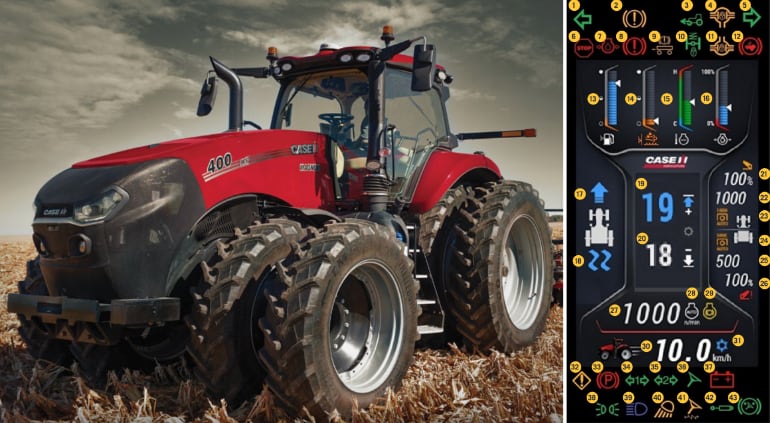
By promptly alerting operators to potential hazards or malfunctions, the instrument cluster contributes to overall safety on the farm. Operators can respond swiftly to warning lights, reducing the risk of accidents or damage to equipment. Some modern instrument clusters are equipped with data logging capabilities, allowing operators to track and analyze performance metrics over time. This data can be invaluable for optimizing tractor operation, identifying trends, and planning maintenance schedules.
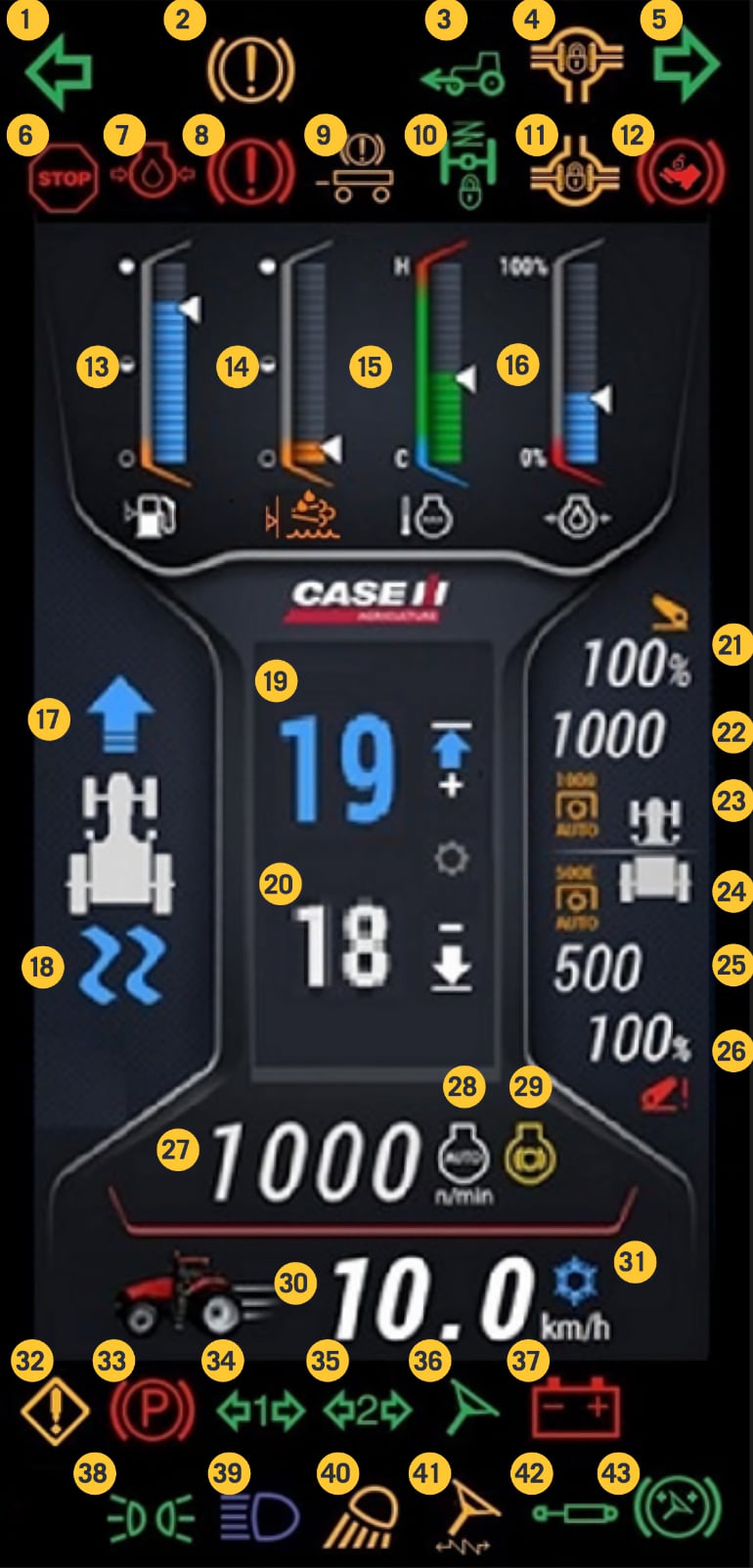
- The left turn signal arrow.
- The brake warning light.
- Tractor’s MFD is engaged – Illuminates when the MFD is engaged, the automatic MFD engages, or when both brake pedals are applied.
- Front Diff-lock is engaged – Illuminates when the Diff-lock is turned on by the operator, the Auto Diff-lock is turned on and the tractor is going in a straight line (N/A on Magnum).
- The right turn signal arrow.
- STOP – warning light Illuminates when there is a fault that requires immediate attention.
- Low engine oil pressure.
- Not applicable in North America.
- Trailer brakes are active – If equipped, this light will come on when the trailer brakes are active.
- Front axle suspension is locked out – This light will come on when the front suspension system is turned off by the operator, or the tractor is in Park.
- Rear axle Diff-lock is engaged – Illuminates when the Diff-lock is turned on by the operator, the Auto Diff-lock is turned on and the tractor is going in a straight line.
- Not Available in North America.
- Fuel level.
- DEF level.
- Engine coolant temperature.
- Air pressure, if present – If not, then engine oil pressure (Engine oil pressure shown).
- Tractor Direction – Indicates tractor direction of travel (forward shown).
- Anti-Jack Knife Feature is shown when activated.
- Forward Target Speed.
- Reverse Target Speed.
- Front Hitch position in percent.
- Front PTO RPM.
- Front PTO engaged.
- Rear PTO engaged.
- Rear PTO speed.
- Rear Hitch position in percent.
- Engine RPM.
- Constant Engine Speed.
- In this location one of the following icons will appear: Engine Power Boost, Engine Compression Brake, or Engine Grid Heater.
- Ground Speed.
- Low temperature warning – for hydraulic oil.
- Yellow Warning Light – Warns operator that a fault exists that needs to be serviced.
- Park break applied light. Comes on when the tractor is placed in “Park”.
- Not applicable in North America.
- Not applicable in North America.
- Guidance On – Guidance system has control of the tractor’s steering system.
- Battery – Alternator not charging the battery.
- Road Lights On – Road lights are on.
- Bright Lights On – High beam road light are on.
- Work Lights On – Work lights are on.
- Guidance Inactive – Guidance is on but not engaged.
- Hydraulic Valve Activated – Illuminates as long there is flow from at least one remote in either direction.
- Not applicable in North America
All Case IH Tractor Dash Symbols & Lights
Case IH often utilize universal tractor dashboard symbols and warning lights in their instrument panels. These symbols, indicators, icons and lights are designed to convey critical information to the operator quickly and efficiently, regardless of the operator’s language or familiarity with the specific tractor model. Universal symbols are often intuitive and easy to understand, even for operators who may not be familiar with the specific tractor model or language used in the manual. Since symbols are not language-dependent, they can effectively communicate important messages to operators regardless of their language proficiency. Case IH is a global brand, and using universal symbols ensures consistency across different regions and markets, making it easier for operators to transition between different tractor models.
General Symbols
| Symbol | Name | Instrument Panel Symbol Description |
|---|---|---|
 |
Master System Warning | Alerts about a critical issue with the tractor’s master system. |
 |
Service | Indicates that the tractor requires servicing or maintenance. |
 |
Malfunction! | See Operator’s Manual |
 |
Malfunction (Alternative) | Indicates the need to consult the operator’s manual for information |
 |
Escape | Allows exiting a menu or mode. |
 |
Safety Alert Symbol | Indicates a safety alert or warning. |
 |
Stop | Indicates a serious tractor malfunction in the tractor’s systems that requires immediate attention. |
 |
Fast | Indicates a high-speed setting or mode. |
 |
Slow | Indicates a low-speed setting or mode. |
 |
Creep | Indicates engagement of the tractor’s super creep gear, which provides exceptionally slow speeds for specific applications. |
 |
High Speed Travel | Indicates that the tractor is operating in high speed travel mode. |
 |
Mid Speed Travel | Shows the tractor is operating at medium speed. |
 |
Low Speed Travel | Signals the tractor is in low-speed mode. |
 |
High Range | Indicates that the tractor is in high gear range, suitable for higher speed operations. |
 |
Mid Range | Shows the transmission is in medium gear range. |
 |
Low Range | Indicates that the tractor is in low gear range, suitable for lower speed operations requiring more power. |
 |
Cruise Control | Indicates that cruise control is engaged. Maintains a constant speed set by the operator. |
 |
Ground Speed | Displays the current ground speed of the tractor, allowing for precise control. |
 |
Speed Limit Switch | Indicates that the speed limit feature is activated, restricting the tractor’s maximum speed. |
 |
Tractor Cruise Control | Indicates that the cruise control feature is activated, maintaining a set speed without manual throttle control. |
 |
Limp Home | Activates a reduced power mode for emergency situations. |
 |
Lock | Indicates that a function or system is locked or engaged. |
 |
Unlock | Indicates that a function or system is unlocked. |
 |
ON (Engaged) | Indicates that a system or function is active or engaged. |
 |
OFF (Disengaged) | Indicates that a system or function is inactive or disengaged. |
 |
Transmission Neutral Indicator | indicates that the tractor is in neutral gear. This light signifies that the transmission is in a neutral position, meaning the tractor is not engaged in any forward or reverse movement. |
 |
Operator Presence Sensor (OPS) | Illuminates when the tractor operator’s seat is unoccupied, reminding the operator to sit properly for safe operation. |
 |
Operator Presence Sensor | Illuminates when the tractor operator’s seat is unoccupied. |
 |
Warning! Corrosive Substance | Indicates the presence of a corrosive substance. Use caution when handling. |
 |
Pressurised Open Carefully | Warns to open a pressurized component carefully to avoid injury. |
Electric-related Dash Symbols
| Symbol | Name | Instrument Panel Symbol Description |
|---|---|---|
 |
Battery Charging Condition | Indicates a malfunction in the tractor’s charging system, typically caused by a faulty alternator or battery, which may result in battery discharge. |
 |
Electrical Power Accessories | Indicates the status of electrical power accessories. |
 |
Master Lighting Switch | Controls the master lighting system. |
 |
Headlight Low Beam | Activates low beam headlights. |
 |
Headlight High Beam | Illuminates the tractor’s headlights for visibility in low-light conditions or during nighttime operation. |
 |
Headlight Flashing | Activates the headlight flash function. |
 |
Work Light | Activates tractor work lights. |
 |
Position Lamps | Controls position lamps. |
 |
Turn Signal | Activates tractor turn signals. |
 |
Turn Signal Trailer | Activates turn signals for trailers. |
 |
Hazard Warning Lights | Activates the hazard lights to warn others of potential danger. |
 |
Audible Warning Device | Indicates the status of the audible warning device. |
| Beacon Light | Controls beacon lights. | |
 |
Windshield Wiper | Activates windshield wipers. |
 |
Windshield Wiper Intermittent | Activates intermittent windshield wiper function. |
 |
Windshield Washer | Activates windshield washer. |
 |
Rear Window Defroster | Activates rear window defroster. |
 |
Air Conditioner | Activates air conditioner. |
 |
Heater Fan | Indicates that the heater fan is operational, providing ventilation or warmth to the cab. |
Engine-related Dash Symbols
| Symbol | Name | Instrument Panel Symbol Description |
|---|---|---|
 |
Fuel Level | Indicates the level of fuel in the tank. |
 |
Diesel Fuel | Indicates the level of diesel fuel in the tank. |
 |
Automatic Fuel Shut-off | Signals that the automatic fuel shut-off system is active, preventing fuel flow. |
 |
Hourmeter / Elapsed Operating Hours | Displays the total operating hours or elapsed time. |
 |
Engine Temperature / Coolant Temperature | Warns the operator when the engine coolant temperature exceeds safe operating limits, indicating potential overheating. |
 |
Low Coolant Level | Warns that the engine coolant level is low and needs to be refilled. |
 |
Engine Intake / Combustion Air Filter | Indicates the condition of the engine air filter. Warns the operator when the air filter becomes clogged or restricted, reducing airflow to the engine and affecting performance. |
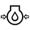 |
Engine Oil Pressure | Indicates the oil pressure in the engine. Warns the operator when engine oil pressure drops below a safe level, indicating potential engine damage or oil system malfunction. |
 |
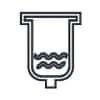
Water Separator | Indicates the status of the water separator in the fuel system. |
 |
Water in Fuel Warning | Indicates that there is water in the diesel fuel. This can be a serious issue, as water in diesel fuel can cause damage to the engine and fuel system. |
 |
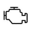
Engine Warning | Indicates the presence of a fault code or error condition in the engine control system, prompting the operator to address the issue promptly. |
 |
Engine Alert | Indicates various functions and warnings related to the engine and its operation (Engine Check). |
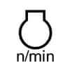 |
Engine Rotational Speed | Displays the rotational speed of the engine. |
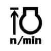 |
Engine Rev Limiter | Limits the maximum engine speed to prevent damage. |
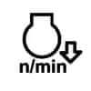 |
Engine Over Speed | Alerts when the engine exceeds its maximum safe speed. |
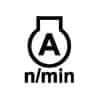 |
Engine RPM Memory A | Stores and recalls a specific engine RPM setting. |
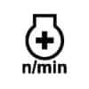 |
Engine RPM Adjuster | Allows adjustment of the engine RPM. |
 |
Engine RPM Increase | Increases the engine RPM. |
 |
Engine Run | Indicates that the engine is running. |
 |
Engine Start | Initiates the engine starting process. |
 |
Engine Stop | Stops the engine. |
 |
Engine Heater (Low Temperature Start Aid) | Illuminates when the engine block heater is in operation, helping to warm the engine for easier starting in cold conditions. Diesel Preheat / Glow Plugs. |
 |
Diesel Engine Preheat | Indicates that the diesel engine preheat function is active, aiding in cold starts. (Low Temperature Start Aid) |
 |
Regeneration | Initiates the regeneration process for the diesel particulate filter. |
 |
Regeneration Inhibit | Prevents regeneration from occurring. |
 |
Regeneration Switch | Activates the regeneration process manually. |
 |
Parked Regeneration | Initiates regeneration while the vehicle is stationary. |
 |
DEF / AdBlue-Level | Indicates the level of Diesel Exhaust Fluid (DEF) or AdBlue. |
 |
DEF / AdBlue Low Level | Alerts when the DEF or AdBlue level is low. |
 |
DEF / AdBlue Poor Quality | Alerts when the quality of DEF or AdBlue is compromised. |
 |
DEF / AdBlue Trouble | Indicates a problem with the DEF or AdBlue system. |
 |
DEF / AdBlue Freeze | Alerts when DEF or AdBlue is at risk of freezing. |
Body-related Dash Symbols
| Symbol | Name | Instrument Panel Symbol Description |
|---|---|---|
 |
Travel Direction | Indicates the current direction of tractor travel. |
 |
Travel Direction Forward | Indicates forward travel direction. |
 |
Travel Direction Rearward | Indicates reverse travel direction. |
 |
4-Wheel Drive On | Indicates that the tractor’s 4-wheel drive system is engaged. |
 |
4-Wheel Drive Off | Indicates that the tractor’s 4-wheel drive system is disengaged. |
 |
Four-wheel On | Engages the four-wheel drive system. |
 |
Four-wheel Automatic | Automatically adjusts the four-wheel drive system based on conditions. |
 |
% Age Slip | Displays the percentage of slippage in the transmission or drive system |
 |
Implement Socket | Shows the status of the implement socket, ensuring proper connection and power supply to attached implements. |
 |
Headland Management System | Manages tractor operations during headland turns. |
 |
Auto Transmission | Engages automatic transmission mode. |
 |
Auto Transmission Sensitivity | Adjusts the sensitivity of the automatic transmission. |
 |
Auto Transmission Road Control | Optimizes transmission settings for road conditions. |
 |
Auto Transmission Field Control | Optimizes transmission settings for field conditions. |
 |
Transmission Oil Filter | Indicates a restricted or clogged transmission oil filter, which can impede hydraulic function and transmission performance. |
 |
Transmission Oil Temperature | Warns the operator when the transmission oil temperature exceeds safe operating levels, indicating potential overheating or insufficient cooling. |
 |
Hydraulic / Transmission Filters | Warns of potential issues with the hydraulic or transmission filters, indicating a need for service or replacement. |
 |
Rear Axle Oil Temperature | Indicates the temperature of the oil in the rear axle, ensuring it remains within safe operating limits. |
 |
Transmission Oil Pressure | Warns of low transmission oil pressure, which could affect transmission performance. |
 |
Gear Shifting Warning | Indicates a problem with gear shifting. |
 |
Clutch | Engages or disengages the tractor clutch. |
 |
Brake | Alerts the operator to low brake fluid levels in the tractor’s brake system, indicating potential brake failure or leakage. |
 |
Parking Brake | Engages the tractor parking brake. Illuminates when the handbrake or parking brake is engaged, reminding the operator to disengage it before driving. |
 |
Air Brake | Indicates the status of the air brake system. |
 |
Brake Failure / Malfunction | Alerts about brake system failure or malfunction. |
 |
Trail Brakes | This light will come on when the trailer brakes are active. |
 |
Stop Lamps | Indicates that the stop lamps are activated, alerting others that the tractor is stopping. |
 |
Brake Fluid Level | Warns that the brake fluid level is low, which may affect braking performance. |
 |
Trailer Brake | Indicates the status of the trailer brake system, ensuring safe towing operations. |
 |
Differential Lock | Indicates engagement of the tractor’s differential lock, enhancing traction in slippery or uneven terrain. |
 |
Differential Lock Automatic | Automatically engages the differential lock based on conditions. |
 |
Steering Wheel Tilt | Adjusts the tilt angle of the steering wheel. |
 |
Steering Wheel Telescope | Adjusts the telescoping position of the steering wheel. |
 |
Automatic Steering Control | Engages automatic steering control. |
 |
Steering Oil Filter | Indicates the status of the steering oil filter. |
 |
Front Suspension | Indicates the status of the front suspension system. |
 |
Front Suspension Automatic | Automatically adjusts the front suspension based on conditions. |
 |
Front Suspension Down | Lowers the front suspension. |
 |
Front Suspension Up | Raises the front suspension. |
 |
Front Suspension Lock | Locks the front suspension in position. |
PTO-related Dash Symbols
| Symbol | Name | Instrument Panel Symbol Description |
|---|---|---|
 |
PTO Off (Disengaged) | Deactivates the power take-off. |
 |
PTO On (Engaged) | Activates the power take-off. |
 |
PTO 540 rpm | Indicates engagement of the tractor’s power take-off (PTO) system at 540 revolutions per minute. |
 |
PTO 540E rpm | Indicates the power take-off speed of 540E rpm. |
 |
PTO 1000 rpm | Indicates engagement of the tractor’s power take-off (PTO) system at 1000 revolutions per minute. |
 |
PTO 1000E rpm | Indicates the power take-off speed of 1000E rpm. |
 |
PTO Front | Indicates the front power take-off is active for front-mounted implements. |
 |
PTO F Front | Indicates the front power take-off is active for front-mounted implements. |
 |
PTO Rear | Indicates the rear power take-off is active for front-mounted implements. |
 |
PTO R Rear | Indicates the rear power take-off is active for front-mounted implements. |
Hydraulic-related Dash Symbols
| Symbol | Name | Instrument Panel Symbol Description |
|---|---|---|
 |
Draft Control | Manages the draft control system for implements. |
 |
Draft Control | Shows the status of the draft control system, which adjusts the implement depth based on soil resistance. |
 |
Position Control | Indicates the position control function, which maintains a set height for the tractor’s implement. |
 |
Position Control | Controls the height or position of attached implements. |
 |
Automatic Draft Operation | Indicates that the automatic draft control system is active, maintaining consistent soil penetration. |
 |
Automatic Tilling Depth Operation | Indicates that the automatic tilling depth control is active. |
 |
Hitch Disabled | Alerts that the tractor’s hitch system is disabled, preventing attachment movements. |
 |
Lift Arm Control Up / Transport | Raises or lowers lift arms for transport mode. |
 |
Lift Arm Control Upward | Raises tractor lift arms. |
 |
Lift Arm Control Down | Lowers tractor lift arms. |
 |
Lift Arm Control Downward | Lowers lift arms. |
 |
Lift Arm Control Block | Locks lift arms in position. |
 |
Lift Arm Control Float | Allows tractor lift arms to float. |
 |
Lift Arm Control Lock | Locks tractor lift arm controls. |
 |
3-Point Lifting / Lowering | Controls the three-point hitch for lifting or lowering implements. |
 |
Lift Arm Height | Indicates the height of the lift arms. |
 |
Position Control – Lowering | Indicates the position control lever is in the lowering position for the implement. |
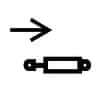 |
Remote Cylinder Retract | Retracts remote hydraulic cylinders. |
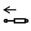 |
Remote Cylinder Extend | Extends remote hydraulic cylinders. |
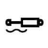 |
Remote Cylinder Float | Allows remote hydraulic cylinders to float. |
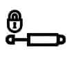 |
Remote Cylinder Lock A | Locks remote hydraulic cylinder control. |
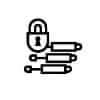 |
Remote Cylinder Lock B | Locks remote tractor hydraulic cylinder control. |
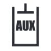 |
Auxiliary Operation Indicator | Indicates that an auxiliary function is active. |
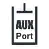 |
Auxiliary Hydraulic Port | Shows the status of auxiliary hydraulic ports. |
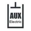 |
AUX Electric Port | Shows the status of the auxiliary electric port. |
 |
AUX Electric Port indicator | Indicates that the auxiliary electric port is active. |
 |
High Flow Indicator | Indicates that the hydraulic system is operating in high flow mode. |
 |
High Flow | Indicates high hydraulic flow is active. |
 |
AUX Hydraulic Port Hold M/F | Indicates the auxiliary hydraulic port hold mode/function is active. |
 |
AUX 14-Pin C Symbol | Shows the status of the 14-pin auxiliary electrical connector. |
 |
Hydraulic Lock Device | Indicates that the hydraulic lock device is engaged, preventing unintended hydraulic movements. |
 |
Hydraulic Oil Temperature | Hydraulic oil temperature warning light. |
 |
Hydraulic Oil Filter | Indicates the status of the hydraulic oil filter. |
Loader-related Dash Symbols
| Symbol | Name | Instrument Panel Symbol Description |
|---|---|---|
 |
Lift Arm Raise / Bucket Up | Indicates the lift arm is raising or the bucket is being lifted |
 |
Lift Arm Lower / Bucket Down | Indicates the lift arm is lowering or the bucket is being lowered |
 |
Loader Bucket Dump | Indicates the Kubota loader bucket is being dumped |
 |
Loader Bucket Rollback / Tilt | Indicates the loader bucket is being rolled back or tilted |
 |
Loader Bucket Float | Indicates the Kubota loader bucket is in float mode |
 |
Loader Quick Hitch Lock | Indicates the loader quick hitch is locked. Locks the loader bucket or attachment into position quickly |
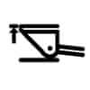 |
Loader Bucket Self Leveling | Indicates the loader bucket is self-leveling. Automatically adjusts the loader bucket to maintain a level position |
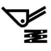 |
Ride Control | Indicates that the ride control feature is active, improving ride comfort by damping loader arm movements. |
 |
Quick Attachment Unlock | Indicates that the quick attachment locking mechanism is disengaged / the quick attachment system is unlocked. |
 |
Self Leveling Indicator | Indicates that the self-leveling function of the loader is active, keeping the bucket level as the arms are raised or lowered. |
 |
Tailgate Safety Cover | Shows the tailgate safety cover is engaged. |
Clear, universally understood symbols help ensure that operators can quickly interpret warning messages and take appropriate action to address any issues, enhancing overall safety on the farm.
- 1100 Series – 1120, 1130, 1140
- 200 Series – 235, 245, 255, 265, 275
- 2100 Series – 2120, 2130, 2140, 2150
- 3200 Utility Series – 3220, 3230
- 4200 Utility Series – 4210, 4230, 4240
- 4WD 94 Series – 4494, 4694, 4894, 4994
- 55 Series – 1255 XL, 1455 XL
- 85 Utility Series – 385, 485, 585, 685, 785, 885, 985
- 85 XL Series – 485XL, 585XL, 685XL, 785XL, 885XL
- 9100 Series – 9110, 9130, 9150, 9170, 9180, 9190
- 9200 Series – 9210, 9230, 9240, 9250, 9260, 9270, 9280
- 9300 Series – 9310, 9330, 9350, 9370, 9370QT, 9380, 9380QT, 9390
- 94 Series – 1394, 1494
- 95 Utility Series – 395, 495, 595, 695, 795, 895, 995
- 96 Series – 1896, 2096
- CL Series – Farmall 80CL, 90CL, 100CL, 110CL, 120CL
- CS Series – CS 48, CS 52, CS 58, CS 63, CS 68, CS 75, CS 78, CS 86, CS 94, CS 110, CS 120, CS 130, CS 150
- CX Utility Series – C50, C60, C70, C80, C90, C100, CX50, CX60, CX70, CX80, CX90, CX100
- DX Series – D35, D40, D45, DX35, DX40, DX45, DX60, Farmall DX48, Farmall DX55
- DXE Series – DX22E, DX25E, DX18E, DX24E
- Farmall Series – Farmall 105V
- Farmall 100A Series – Farmall 110A, 120A, 125A, 130A, 140A
- Farmall A Series – Farmall 35A, 40A, 45A, 50A, 55A, 60A, 65A, 70A, 75A
- Farmall B Series – Farmall 30B, 35B, 40B, 50B
- Farmall C Series – Farmall 30C, 35C, 40C, 45C, 50C, 55C, 65C, 75C, 85C, 90C, 95C, 100C, 105C, 110C, 115C, 120C
- Farmall Compact Series – Farmall 31, 35, 40, 45, 50
- Farmall DX Series – Farmall DX21, DX24, DX29, DX33
- Farmall M Series – Farmall 110M, 120M
- Farmall N Series – Farmall 75N, 80N, 95N, 100N, 105N, 110N
- Farmall U Series – Farmall 85U, 95U, 105U, 110U, 115U, 120U
- Farmall Utility Series – Farmall 70, 80, 90, 95
- Farmall V Series – Farmall 80V, 110V
- JX Series – JX55, JX60, JX65, JX70, JX75, JX80, JX85, JX90, JX95
- JXC Series – JX1060C, JX1070C, JX1075C, JX1085C, JX1095C
- JXN Series – JX1075N, JX1095N
- JXU Series – JXU 75, JXU 85, JXU 95, JXU 105, JXU 115
- JXU Maxxima Series – JX80U, JX90U, JX100U, JX1070U, JX1080U, JX1090U, JX1100U
- Luxxum Series – Luxxum 100, 110, 120
- MXU Maxxum Series – MXU100, MXU110, MXU115 Value, MXU125, MXU130 Value, MXU135
- Magnum Series – 7110, 7120, 7130, 7140, 7150, MX180, MX200, MX210, MX215, MX220, MX230, MX240, MX245, MX255, MX270, MX275, MX285, MX305, Magnum 180, 190, 200, 210, 215, 220, 225, 235, 240, 245, 250, 260, 275, 280, 290, 305, 310, 315, 335, 340, 370, 380, 400
- Magnum 7200 Series – 7210, 7220, 7230, 7240, 7250
- Magnum 8900 Series – 8910, 8920, 8930, 8940, 8950
- Maxxum Series – 5120, 5130, 5140, 5150, 5220, 5230, 5240, 5250, MX100, MX110, MX120, MX135, MX150, MX170, MXM120, MXM130, MXM140, MXM155, MXM175, MXM190, Maxxum 110, 115, 120, 125, 130, 135, 140, 145, 150
- Optum Series – Optum 270, 300
- PJ Series – PJ55, PJ65, PJ75
- Puma Series – Puma 115, 125, 130, 140 X, 145, 150 X, 155, 160, 165 X, 170, 180, 185, 195, 200, 210, 215, 220, 225, 230, 240
- Quadtrac Series – STX380QT, STX430QT, STX480QT, STX530QT
- Steiger 4WD Series – Steiger 370, 420, 425, 470, 475, 525, 540, 555, 580, 595, 620, 645
- Steiger Quadtrac Series – Steiger 470 Quadtrac, 475, 525, 540, 555, 580, 595, 620, 645, 715
- Steiger Rowtrac Series – Steiger 350 Rowtrac, 370, 400, 420, 425, 450, 470, 475, 500, 525
- Steiger STX Series – STX275, STX280, STX325, STX330, STX375, STX375QT, STX380, STX425, STX425QT, STX430, STX440, STX440QT, STX450, STX450QT, STX480, STX500, STX500QT, STX530
- Vestrum Series – Vestrum 100, 110, 120, 130
While universal symbols are common, Case IH may also include text alongside symbols for additional clarity, especially for less common or more complex warnings. This combination ensures that operators have access to all necessary information to operate the tractor safely and effectively.
Colors of Case IH Tractor Warning Lights
The colors of warning lights on Case IH tractors and equipment serve as critical indicators for the operator, providing essential information about the machine’s status and any potential issues that may arise during operation. Understanding these colors can help ensure safe and efficient use of the equipment.
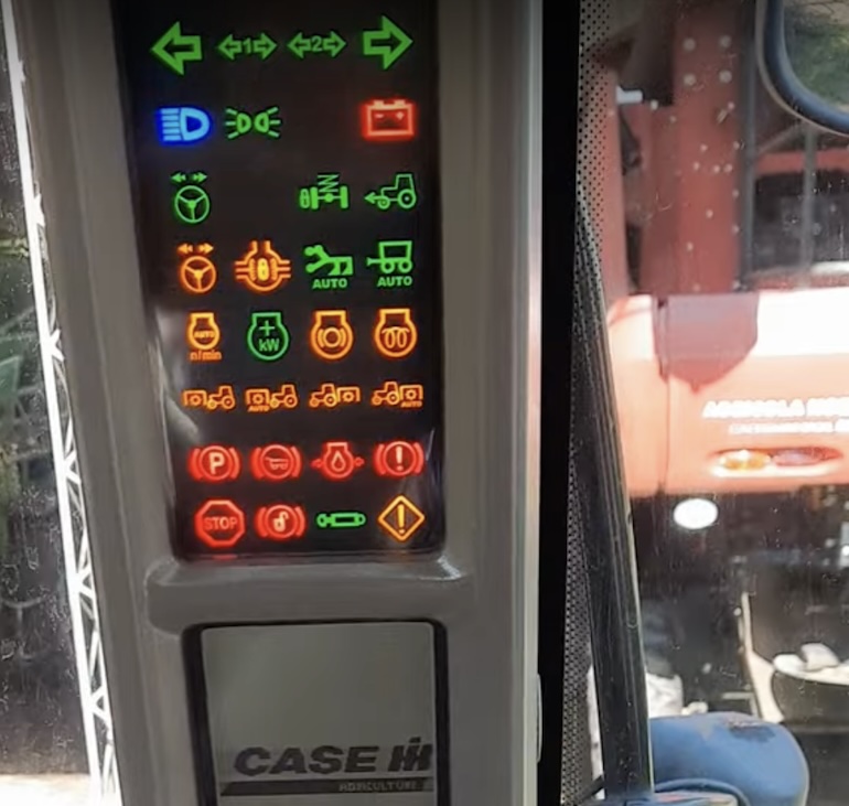
Typically, warning lights are categorized by color, each representing different levels of urgency and types of alerts:
- Red Warning Lights: These lights indicate critical issues that require immediate attention, such as engine overheating or low oil pressure. Ignoring red warnings can lead to severe damage or failure.
- Amber/Yellow Warning Lights: These lights signal caution and suggest that the operator should check the system soon. They may indicate low fuel levels or maintenance reminders.
- Green Indicator Lights: These lights indicate that specific systems are functioning correctly, such as headlights being on or the PTO being engaged.
- Blue Indicator Lights: Often used for auxiliary functions, such as high beam headlights.
By familiarizing themselves with these warning light colors, operators can quickly assess the condition of their Case IH equipment and take appropriate action, ensuring both safety and optimal performance.
How to Reset Case IH Warning Lights?
The service light on Case IH tractors can typically be reset by accessing the tractor’s diagnostic menu and selecting the option to reset the service interval. This can often be done without needing to return to the dealer. The specific steps may vary depending on the tractor model, but generally involve navigating the tractor’s display or control panel to find the service reset function.
For example, on the Case IH 7110 Magnum, the service indicator can be reset by entering a specific key sequence on the tractor’s control panel. On the Case IH 4210, the orange exclamation mark warning light can be reset in a similar way by accessing the diagnostic menu. If the tractor has a “Stop” warning light, this may indicate an issue that requires further troubleshooting, such as checking fluid levels and performing a parked regeneration. If the light persists after these steps, the tractor may need to be serviced by a technician.
Resetting Case IH tractor warning lights typically involves navigating the tractor’s diagnostic menu and selecting the appropriate reset function, which can often be done without needing to return to the dealer. However, some warning lights may indicate more serious issues that require further diagnosis and repair:
Here are general steps to reset warning lights:
- Identify the Warning: First, identify which warning light is illuminated on the instrument cluster. Refer to the tractor’s operator’s manual or warning light guide to understand what the light indicates.
- Address the Issue: Determine the cause of the warning light. It could be due to various factors such as low fluid levels, engine malfunctions, hydraulic system issues, or electrical problems. Inspect the tractor thoroughly to identify and resolve the underlying issue.
- Correct the Problem: Once you’ve identified the issue, take appropriate steps to address it. This might involve refilling fluids, checking and repairing connections, replacing damaged components, or performing maintenance tasks.
- Disconnect Battery: In some cases, especially for electrical issues, disconnecting the tractor’s battery for a few minutes may reset the warning lights. However, this should be done cautiously, and it’s essential to ensure that disconnecting the battery won’t cause any unintended consequences or data loss in the tractor’s systems.
- Consult the Manual: If you’re unsure about how to address the specific issue or reset the warning light, consult the tractor’s operator’s manual or contact a Case IH authorized service center for guidance.
- Verify Reset: After addressing the underlying issue, start the tractor and verify if the warning light has turned off. If it remains illuminated, double-check that the problem has been resolved correctly.
- Monitor Operations: After resetting the warning light, monitor the tractor’s operations closely for any signs of recurring issues. If the warning light reappears or if you encounter any new problems, address them promptly to prevent potential damage or safety hazards.
It’s important to remember that resetting warning lights without addressing the underlying issues may temporarily clear the warning, but it won’t solve the problem. Always prioritize diagnosing and fixing the root cause of the warning light to ensure the safe and efficient operation of the tractor. If you’re uncertain about performing any maintenance or troubleshooting tasks, seek assistance from qualified professionals.
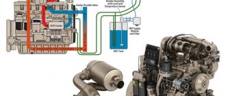


Why does CASE IH create inactive warning lights on the tractor dashboard / instrument cluster?
Creating inactive warning lights on a tractor dashboard might seem counterintuitive, but there are a few reasons why manufacturers like CASE IH might do this. Sometimes, manufacturers install warning lights for features or functionalities that the tractor doesn’t currently have but might be added in future models or through software updates. This helps in standardizing the dashboard layout across different models and simplifies future upgrades. Case IH often produce a range of models with varying features and capabilities. By including inactive warning lights across these models, they maintain consistency in the dashboard layout. This uniformity can make it easier for operators who work with different tractor models to adapt and operate them efficiently. Designing and manufacturing unique instrument clusters for each tractor model can be costly. By incorporating inactive warning lights, manufacturers can reuse the same dashboard design across multiple models, reducing production costs.