- Kubota Warning Lights & Dash Symbols for Tractors
- MX Series Indicators & Warning Lights
- M6 Series Indicators & Warning Lights
- M8 Series Indicators & Warning Lights
- Dash Symbols / Warning Lights for Kubota Skid Steers
- Dash Symbols / Warning Lights for Kubota Wheel Loaders
- Dash Symbols / Warning Lights for Kubota Excavators
- All Kubota Instrument Panel Symbols & Lights
- General Dash Symbols
- Engine-related Dash Symbols
- Body-related Dash Symbols
- PTO-related Dash Symbols
- Hydraulic-related Dash Symbols
- Electric-related Dash Symbols
- Excavator Dash Symbols
- SSL / CTL / Wheel Loader Dash Symbols
- Color of Kubota Warning Lights
- How to Reset Kubota Warning Lights?
Kubota dashboard symbols and warning lights help operators monitor vital functions and respond promptly to any issues to ensure safe and efficient operation of heavy equipment across different applications. Always refer to the equipment’s manual for detailed information on dash symbols and warning indicators / lights specific to each model.
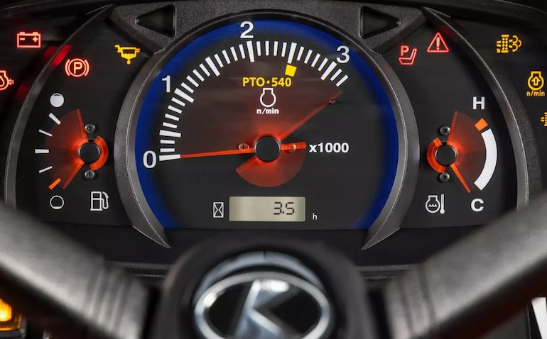
These are just a few examples of Kubota dashboard symbols and warning lights. It’s essential for operators to familiarize themselves with their specific equipment model’s instrument cluster layout and consult the operator’s manual for detailed information on each symbol’s meaning and appropriate actions to take. Whether you’re operating a tractor in the field or maneuvering a skid steer on a construction site, understanding these symbols is crucial for safe and efficient operation.
Kubota Warning Lights & Dash Symbols for Tractors
To ensure smooth operation and safe use of these machines, Kubota incorporates a range of warning lights and dashboard symbols to alert operators to potential issues and provide essential information about the tractor’s status. Understanding these tractor warning lights and symbols is crucial for maintaining optimal performance and preventing mechanical problems. From engine temperature warnings to hydraulic oil indicators, we’ll decipher the various signals that Kubota tractors use to communicate important information to operators. Whether you’re a seasoned farmer or a novice tractor user, this guide will help you navigate the instrument cluster and respond appropriately to any alerts that may arise during operation.
MX Series Indicators & Warning Lights
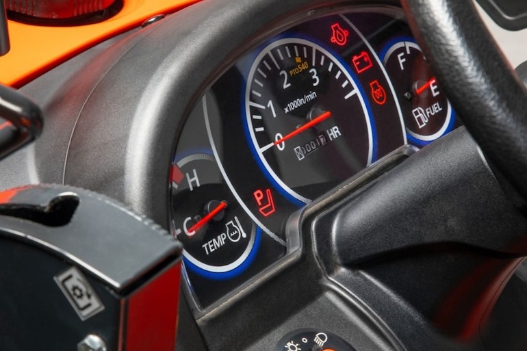
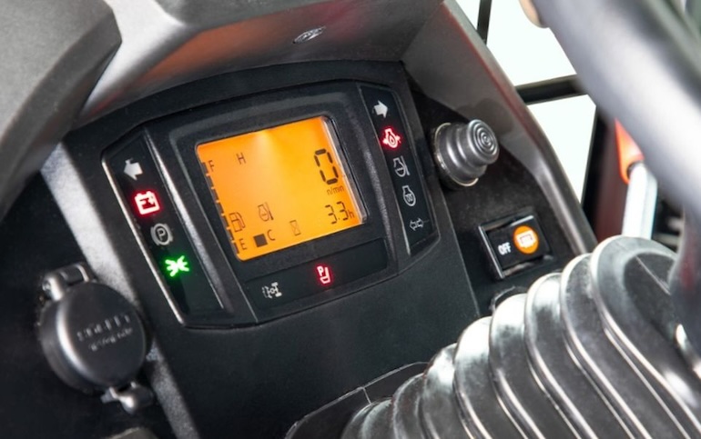
Kubota MX series multipurpose tractor instrument panel and controls (MX5400, MX5400 Cab, MX6000, MX6000 Cab, etc):
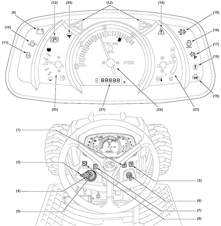
- DPF INHIBIT switch.
- Parked regeneration switch.
- Turn signal light switch.
- Head light switch.
- Hazard light switch.
- Key switch.
- Stationary PTO switch.
- Horn button [CAB type only].
- Electrical charge warning indicator.
- Engine oil pressure warning indicator.
- Glow plug indicator.
- Parking brake warning indicator.
- Turn signal / hazard light indicator.
- Master system warning indicator.
- Regeneration indicator.
- Engine RPM increase indicator.
- Parked regeneration.
- Engine warning indicator.
- Emission indicator.
- Fuel gauge.
- Hour meter + tractor error code indicator.
- Tachometer.
- Coolant temperature gauge.
- Water separator filter indicator
M6 Series Indicators & Warning Lights
Kubota M6 series mid-size utility tractor instrument panel and controls (M6-101, M6-111, M6-131, M6-141, etc):
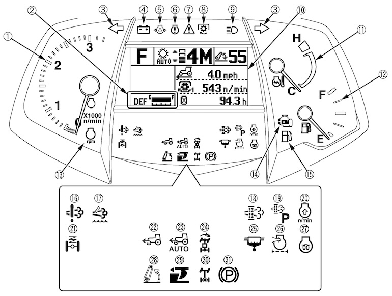
- Tachometer.
- DEF / AdBlue gauge.
- Turn signal / Hazard light indicator.
- Electrical charge warning indicator.
- Engine oil pressure warning indicator.
- Engine warning indicator.
- Master system warning indicator.
- PTO clutch indicator.
- High-beam indicator.
- LCD (variety of information necessary to operate the tractor + error codes. Further, part of the display can be modified by the operator as required).
- Coolant temperature gauge.
- Fuel gauge.
- Constant RPM management indicator.
- Emission indicator.
- Fuel level indicator.
- DEF / AdBlue system warning indicator.
- DEF / AdBlue warning indicator.
- Regeneration indicator.
- Parked regeneration indicator.
- Engine RPM increase indicator.
- Front suspension indicator [Front suspension type].
- 4WD indicator.
- Auto 4WD indicator.
- Bi-speed turn indicator.
- Water separator indicator.
- Air cleaner indicator.
- Heater indicator.
- 3-Point Lifting / Lowering indicator.
- Draft indicator.
- Rear wheel differential lock indicator.
- Parking brake warning indicator
M8 Series Indicators & Warning Lights
Kubota M8 series row crop tractor instrument cluster (M8-181, 8-201, etc):
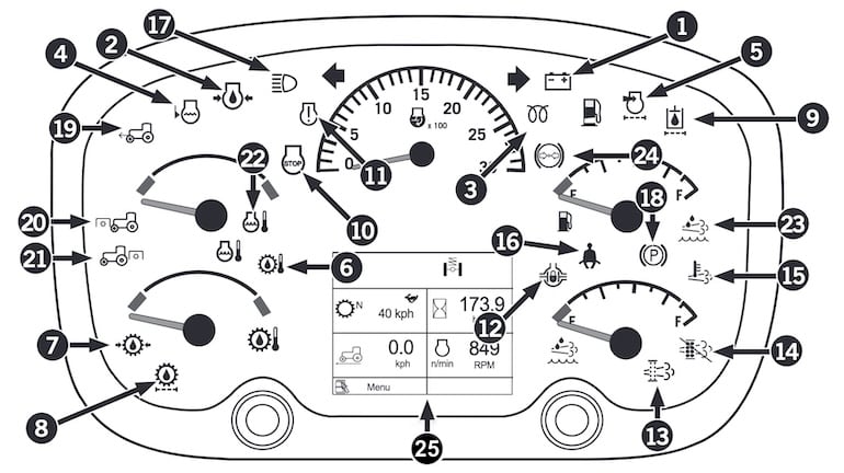
- Alternator Charge Indicator: Illuminates steady and sounds an alarm if alternator is not charging battery.
- Engine Oil Pressure: Illuminates when low engine oil pressure is detected.
- Inlet Heater/Ready to Start: Illuminates when key is turned to the run position and is cold enough outside to activate grid heater.
- Coolant Level Low: Illuminates when coolant in reservoir is low.
- Air Filter Restriction: Illuminates if a fault has existed for 10 seconds.
- Transmission Oil Temperature: Flashes when high transmission oil temp detected (above 99ºC / 210 ºF).
- Transmission Oil Pressure: Illuminates and sounds an alarm indicating low transmission oil pressure.
- Transmission Oil Filter: Illuminates indicating a filter bypass condition due to a blocked filter.
- Hydraulic Oil Filter: Illuminates indicating a filter bypass condition and no longer filtering oil returning to the reservoir.
- Stop Engine: Illuminates when a critical condition has been detected.
- Engine Warning Light: Yellow for non-critical and maintenance and red for critical faults.
- Differential Locks (option): Illuminates when the differential lock button is engaged on tractors equipped with differential locks.
- Diesel Particulate Filter (DPF) light: DPF filter is filling — may be flashing and / or used with the engine stop or warning light.
- Regeneration inhibit light on: Regeneration has been stopped.
- High exhaust temperature light on: Higher than normal exhaust temperatures may exist due to DPF regeneration.
- Seat Belt: Illuminates when the ignition switch is turned to the RUN position and stays illuminated for 5 seconds to remind the operator to fasten the seat belt.
- High Beams: Illuminates when tractor lights are switched to high beam.
- Parking Brake: Illuminates when the parking brake is applied. (Absent Operator Warning: If you leave the operator seat for more than 3 seconds while the engine is running, the parking brake lamp will flash and an audible alarm will sound.)
- Front Wheel Assist: When the service brake pedals are applied, the front wheel assist is automatically activated so that both front and rear wheels assist in braking.
- Front PTO: Illuminates when front pto is enabled.
- Rear PTO: Illuminates when rear pto is enabled.
- Engine Coolant Temperature: Illuminates when engine coolant temperature has risen above acceptable limits.
- Diesel Exhaust Fluid (DEF): DEF level is low.
- Brake Pressure is Normal: This icon will appear if the brake pressure is normal.
- LCD display for tractor information screens.
Dash Symbols / Warning Lights for Kubota Skid Steers
To help operators monitor the machine’s performance and ensure safe operation, Kubota incorporates a variety of warning lights and dashboard symbols into the design of their skid steers. In this guide, we’ll explore the meaning behind Kubota skid steer dash symbols and warning lights. From engine-related indicators to hydraulic system alerts, understanding these symbols is essential for maintaining optimal performance and preventing potential issues during operation. By familiarizing yourself with these indicators, you can ensure safe and efficient operation of your Kubota skid steer loader.
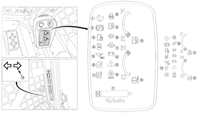
- Speed indicator lamp.
- Parking brake lamp.
- Hydraulic lock lamp.
- AUX operation lamp.
- Ride control (KSR) lamp.
- Coolant temperature warning lamp.
- Hydraulic oil temperature warning lamp.
- Glow plug lamp.
- Remaining fuel warning lamp.
- DPF regeneration indicator.
- Engine oil pressure warning lamp.
- Battery charge lamp.
- Warning lamp.
- Engine rev up warning lamp.
- Fuel gauge indicator.
- Coolant temperature gauge.
- Hour meter & Error code number (for detail, refer to “List of Error Code Numbers”)
- Turn signal indicator (Option).
- AUX electrical mode change lamp.
- Floating lamp.
- Fuel gauge indicator & Remaining fuel warning lamp.
- Coolant temperature gauge & coolant temperature warning lamp.
Dash Symbols / Warning Lights for Kubota Wheel Loaders
From engine-related dash indicators to hydraulic system warning lights, understanding these symbols is crucial for maintaining optimal performance and preventing potential issues during operation. Whether you’re a seasoned operator or new to using Kubota wheel loaders, this guide will provide insights into interpreting the dashboard symbols and responding appropriately to any warnings that may arise.
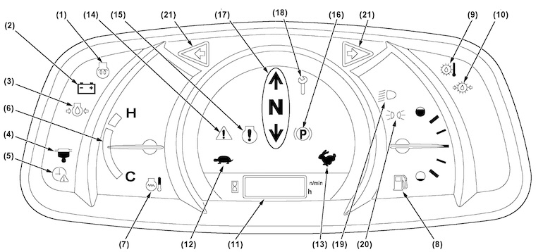
- Glow plug indicator.
- Battery charge indicator.
- Engine oil pressure warning indicator.
- Water separator filled-up indicator.
- Clock setting request indicator.
- Coolant temperature gauge.
- Coolant temperature warning indicator.
- Fuel gauge.
- LST oil-temperature warning indicator.
- LST charge-pressure-warning indicator.
- LCD – digital diagnostic indicator (Error display).
- Low travel speed indicator.
- High travel speed indicator.
- Warning indicator.
- Engine warning indicator.
- Parking brake indicator.
- Forward, backward, and neutral indicator.
- Periodic check indicator.
- Headlight indicator.
- Clearance light indicator.
- Hazard / turn signal indicator.
Dash Symbols / Warning Lights for Kubota Excavators
Whether you’re a seasoned operator or new to using Kubota excavators, this guide will provide valuable insights into interpreting the dashboard symbols and responding appropriately to any warnings that may arise.
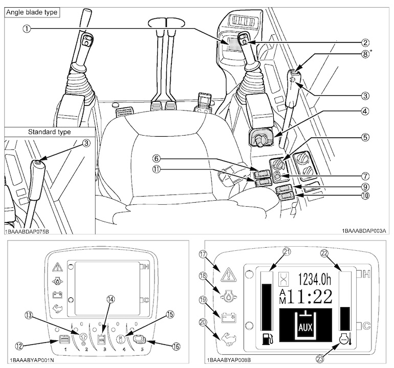
- LCD display.
- Horn switch.
- Travel speed switch.
- Starter switch.
- Throttle potentiometer.
- Light switch.
- Auto idle control switch.
- Angle blade control switch (*Angle blade type only).
- Eco mode switch.
- DPF inhibit switch.
- Beacon light switch.
- User setting switch (Switch 1).
- Overload Warning Switch (Switch 2).
- AUX port enable switch (Switch 3).
- Information switch (Switch 4).
- Display selector switch (Switch 5).
- Warning lamp.
- Oil lamp.
- Charging lamp.
- Speed indicator light.
- Fuel gauge.
- Coolant temperature gauge.
- Coolant temperature sensor marker.
By familiarizing yourself with these indicators, you can operate your Kubota excavator with confidence and efficiency.
All Kubota Instrument Panel Symbols & Lights
By familiarizing yourself with Kubota’s instrument panel symbols and lights, you’ll be better equipped to respond to any warnings or indicators that may arise during your work.
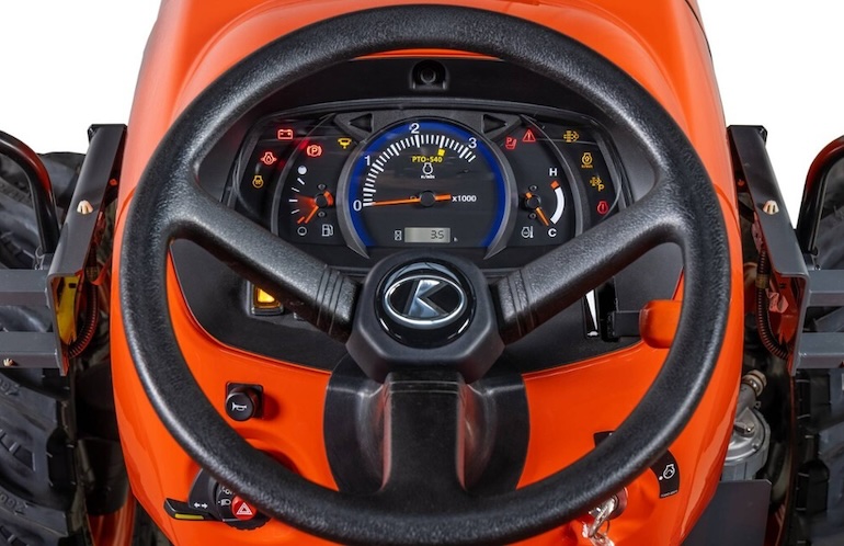
From monitoring engine temperature to ensuring proper engagement of hydraulic systems, these symbols play a vital role in optimizing equipment performance and minimizing downtime.
General Dash Symbols
| Symbol | Name | Description |
|---|---|---|
 |
Safety Alert Symbol | Indicates a safety alert or warning |
 |
Master System Warning | Alerts about a critical issue with the equipment master system |
 |
Stop | The STOP indicator is a critical indicator of a serious problem that must be corrected immediately to ensure safe operation of the equipment. |
 |
Fast | Indicates a high-speed setting or mode |
 |
Slow | Indicates a low-speed setting or mode |
 |
Creep | Indicates engagement of the super creep gear, which provides exceptionally slow speeds for specific applications. |
 |
Lock | Indicates that a function or system is locked or engaged |
 |
Unlock | Indicates that a function or system is unlocked |
 |
ON (Engaged) | Indicates that a system or function is active or engaged |
 |
OFF (Disengaged) | Indicates that a system or function is inactive or disengaged |
 |
Transmission Neutral Indicator | indicates that the tractor is in neutral gear. This light signifies that the transmission is in a neutral position, meaning the equipment is not engaged in any forward or reverse movement. |
 |
Operator Presence Sensor (OPS) | Illuminates when the operator’s seat is unoccupied, reminding the operator to sit properly for safe operation. |
 |
Operator Presence Control | This safety feature ensures that the tractor or Kubota equipment will not operate unless there is sufficient weight on the seat to indicate the presence of an operator. |
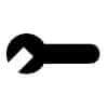 |
Service | Indicates that the equipment requires servicing or maintenance |
 |
Information | This switch is used to control the display of information on the instrument cluster, such as engine hours, fuel level, and other operational data. The specific meaning of the symbol may vary depending on the model of the equipment. |
 |
Read Operator’s Manual | Indicates the need to consult the operator’s manual for information |
 |
Escape | Allows exiting a menu or mode |
Engine-related Dash Symbols
| Symbol | Name | Description |
|---|---|---|
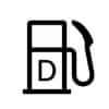 |
Diesel Fuel | Indicates the level of diesel fuel in the tank |
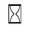 |
Hourmeter / Elapsed Operating Hours | Displays the total operating hours or elapsed time |
 |
Engine Temperature / Coolant Temperature | Warns the operator when the engine coolant temperature exceeds safe operating limits, indicating potential overheating. |
 |
Engine Intake / Combustion Air Filter | Indicates the condition of the engine air filter. Warns the operator when the air filter becomes clogged or restricted, reducing airflow to the engine and affecting performance. |
 |
Engine Oil Pressure | Indicates the oil pressure in the engine. Warns the operator when engine oil pressure drops below a safe level, indicating potential engine damage or oil system malfunction. |
 |
Water Separator | Indicates the status of the water separator in the fuel system |
 |
Engine Warning | Indicates the presence of a fault code or error condition in the engine control system, prompting the operator to address the issue promptly. |
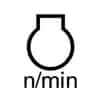 |
Engine Rotational Speed | Displays the rotational speed of the Kubota engine |
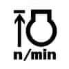 |
Engine Rev Limiter | Limits the maximum engine speed to prevent damage |
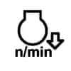 |
Engine Over Speed | Alerts when the engine exceeds its maximum safe speed |
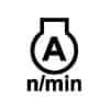 |
Engine RPM Memory A | Stores and recalls a specific engine RPM setting |
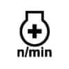 |
Engine RPM Adjuster | Allows adjustment of the engine RPM |
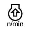 |
Engine RPM Increase | Increases the engine RPM |
 |
Engine Run | Indicates that the engine is running |
 |
Engine Start | Initiates the engine starting process |
 |
Engine Stop | Stops the Kubota engine |
 |
Engine Heater (Low Temperature Start Aid) | Illuminates when the engine block heater is in operation, helping to warm the engine for easier starting in cold conditions. Diesel Preheat / Glow Plugs |
 |
Regeneration | Initiates the regeneration process for the diesel particulate filter |
 |
Regeneration Inhibit | Prevents regeneration from occurring |
 |
Regeneration Switch | Activates the regeneration process manually |
 |
Parked Regeneration | Initiates regeneration while the vehicle is stationary |
 |
DEF / AdBlue-Level | Indicates the level of Diesel Exhaust Fluid (DEF) or AdBlue |
 |
DEF / AdBlue Low Level | Alerts when the DEF or AdBlue level is low |
 |
DEF / AdBlue Poor Quality | Alerts when the quality of DEF or AdBlue is compromised |
 |
DEF / AdBlue Trouble | Indicates a problem with the DEF or AdBlue system |
 |
Thawing DEF / AdBlue | Alerts when DEF or AdBlue is at risk of freezing |
Body-related Dash Symbols
| Symbol | Name | Description |
|---|---|---|
 |
Travel Direction | Indicates the current direction of tractor travel |
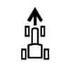 |
Travel Direction Forward | Indicates forward travel direction |
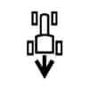 |
Travel Direction Rearward | Indicates reverse travel direction |
 |
Cruise Control | Maintains a constant speed set by the operator |
 |
Limp Home | Activates a reduced power mode for emergency situations |
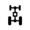 |
4-Wheel Drive On | Indicates engagement of the tractor’s four-wheel-drive (4WD) system with differential lock, providing increased traction in challenging terrain. |
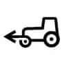 |
Four-wheel On | Engages the four-wheel drive system |
 |
Four-wheel Automatic | Automatically adjusts the four-wheel drive system based on conditions |
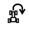 |
Headland Management System | Manages tractor operations during headland turns |
 |
Auto Transmission | Engages automatic transmission mode |
 |
Auto Transmission Sensitivity | Adjusts the sensitivity of the automatic transmission |
 |
Auto Transmission Road Control | Optimizes transmission settings for road conditions |
 |
Auto Transmission Field Control | Optimizes transmission settings for field conditions |
 |
Transmission Oil Filter | Indicates a restricted or clogged transmission oil filter, which can impede hydraulic function and transmission performance. |
 |
Transmission Oil Temperature | Warns the operator when the transmission oil temperature exceeds safe operating levels, indicating potential overheating or insufficient cooling. |
 |
Gear Shifting Warning | Indicates a problem with gear shifting |
 |
Clutch | Engages or disengages the clutch |
 |
Brake | Alerts the operator to low brake fluid levels in the brake system, indicating potential brake failure or leakage. |
 |
Parking Brake | Engages the parking brake. Illuminates when the handbrake or parking brake is engaged, reminding the operator to disengage it before driving. |
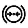 |
Air Brake | Indicates the status of the air brake system |
 |
Brake Failure / Malfunction | Alerts about brake system failure or malfunction |
 |
Differential Lock | Indicates engagement of the differential lock, enhancing traction in slippery or uneven terrain |
 |
Differential Lock Automatic | Automatically engages the differential lock based on conditions. |
 |
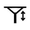
Steering Wheel Tilt | Adjusts the tilt angle of the steering wheel |
 |
Steering Wheel Telescope | Adjusts the telescoping position of the steering wheel |
 |
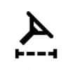
Automatic Steering Control | Engages automatic steering control |
 |
Steering Oil Filter | Indicates the status of the steering oil filter |
 |
Front Suspension | Indicates the status of the front suspension system |
 |
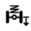
Front Suspension Automatic | Automatically adjusts the front suspension based on conditions |
 |
Front Suspension Down | Lowers the front suspension |
 |
Front Suspension Up | Raises the front suspension |
 |
Front Suspension Lock | Locks the front suspension in position |
PTO-related Dash Symbols
| Symbol | Name | Description |
|---|---|---|
 |
PTO Off (Disengaged) | Deactivates the power take-off |
 |
PTO On (Engaged) | Activates the power take-off |
 |
PTO 540 rpm | Indicates engagement of the tractor’s power take-off (PTO) system at 540 revolutions per minute |
 |
PTO 540E rpm | Indicates the power take-off speed of 540E rpm |
 |
PTO 1000 rpm | Indicates engagement of the tractor’s power take-off (PTO) system at 1000 revolutions per minute |
 |
PTO 1000E rpm | Indicates the power take-off speed of 1000E rpm |
 |
PTO Front | Indicates the front power take-off is active for front-mounted implements |
 |
PTO F Front | Indicates the front power take-off is active for front-mounted implements |
 |
PTO Rear | Indicates the rear power take-off is active for front-mounted implements |
 |
PTO R Rear | Indicates the rear power take-off is active for front-mounted implements |
Hydraulic-related Dash Symbols
| Symbol | Name | Description |
|---|---|---|
 |
Draft Control | Manages the draft control system for implements |
 |
Position Control | Controls the height or position of attached implements |
 |
Lift Arm Control Up / Transport | Raises or lowers lift arms for transport mode |
 |
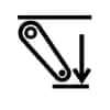
Lift Arm Control Upward | Raises tractor lift arms |
 |
Lift Arm Control Down | Lowers tractor lift arms |
 |
Lift Arm Control Downward | Lowers lift arms |
 |
Lift Arm Control Block | Locks lift arms in position |
 |
Lift Arm Control Float | Allows tractor lift arms to float |
 |
Lift Arm Control Lock | Locks tractor lift arm controls |
 |
3-Point Lifting / Lowering | Controls the three-point hitch for lifting or lowering implements |
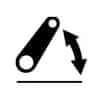 |
Lift Arm Height | Indicates the height of the lift arms |
 |
Position Control – Lowering | Indicates the position control lever is in the lowering position for the implement. |
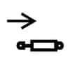 |
Remote Cylinder Retract | Retracts remote hydraulic cylinders |
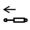 |
Remote Cylinder Extend | Extends remote hydraulic cylinders |
 |
Remote Cylinder Float | Allows remote hydraulic cylinders to float |
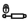 |
Remote Cylinder Lock A | Locks remote hydraulic cylinder control |
 |
Remote Cylinder Lock B | Locks remote tractor hydraulic cylinder control |
 |
Auxiliary Operation Indicator | Indicates that an auxiliary function is active. |
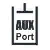 |
Auxiliary Hydraulic Port | Shows the status of auxiliary hydraulic ports. |
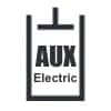 |
AUX Electric Port | Shows the status of the auxiliary electric port. |
 |
AUX Electric Port indicator | Indicates that the auxiliary electric port is active. |
 |
High Flow Indicator | Indicates that the hydraulic system is operating in high flow mode. |
 |
High Flow | Indicates high hydraulic flow is active. |
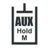 |
AUX Hydraulic Port Hold M/F | Indicates the auxiliary hydraulic port hold mode/function is active. |
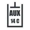 |
AUX 14-Pin C Symbol | Shows the status of the 14-pin auxiliary electrical connector. |
 |
Hydraulic Lock Device | Indicates that the hydraulic lock device is engaged, preventing unintended hydraulic movements. |
 |
Hydraulic Oil Temperature | Hydraulic oil temperature warning light. |
 |
Hydraulic Oil Filter | Indicates the status of the hydraulic oil filter. |
Electric-related Dash Symbols
| Symbol | Name | Description |
|---|---|---|
 |
Battery Charging Condition | Indicates a malfunction in the charging system, typically caused by a faulty alternator or battery, which may result in battery discharge. |
 |
Electrical Power Accessories | Indicates the status of electrical power accessories |
 |
Master Lighting Switch | Controls the master lighting system |
 |
Headlight Low Beam | Activates low beam headlights |
 |
Headlight High Beam | Illuminates the headlights for visibility in low-light conditions or during nighttime operation |
 |
Headlight Flashing | Activates the headlight flash function |
 |
Work Light | Activates work lights |
 |
Position Lamps | Controls position lamps |
 |
Turn Signal | Activates turn signals |
 |
Turn Signal Trailer | Activates turn signals for trailers |
 |
Hazard Warning Lights | Activates the hazard lights to warn others of potential danger |
 |
Horn | Indicates the position of the horn switch and whether the horn is activated or not |
| Beacon Light | Controls beacon lights | |
 |
Windshield Wiper | Activates windshield wipers |
 |
Windshield Wiper Intermittent | Activates intermittent windshield wiper function |
 |
Windshield Washer | Activates windshield washer |
 |
Rear Window Defroster | Activates rear window defroster |
 |
AUX Electrical Mode Change | Allows the operator to change the electrical mode for auxiliary functions, enabling the use of specific electrical features or attachments on the tractor or excavator |
Excavator Dash Symbols
| Symbol | Name | Description |
|---|---|---|
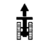 |
Toward the Front | Excavator – Overhead view, movement toward the front |
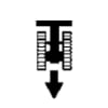 |
Toward the Rear | Excavator – Overhead view, movement toward the rear |
 |
Grease | Indicates the need for greasing the excavator’s components |
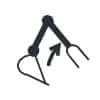 |
Boom Up / Raise | Indicates the upward movement of the excavator boom |
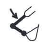 |
Boom Down / Lower | Indicates the excavator boom downward movement |
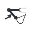 |
Arm In / Crowd | Indicates the inward movement of the excavator arm |
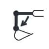 |
Arm Out / Up | Indicates the outward movement or raising of the excavator arm |
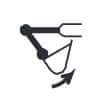 |
Bucket Crowd | Indicates the inward movement of the excavator bucket |
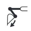 |
Bucket Down | Indicates the excavator bucket downward movement |
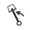 |
Boom Swing (Left) | Indicates the excavator boom left swing movement |
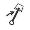 |
Boom Swing (Right) | Indicates the excavator boom right swing movement |
 |
Dozer Raise | Indicates the bulldozer blade upward movement |
 |
Dozer Lower | Indicates the Kubota dozer blade downward movement |
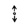 |
Operation direction of control lever | Indicates the direction of the excavator control lever movement |
 |
Operation direction of control lever | Indicates the direction of movement controlled by the lever |
 |
Overload Warning Switch | Activates when the excavator experiences an overload condition, warning the operator of potential issues |
SSL / CTL / Wheel Loader Dash Symbols
| Symbol | Name | Description |
|---|---|---|
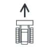 |
Forward | Indicates the loader is moving forward |
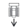 |
Backward | Indicates the loader is moving backward |
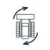 |
Turn Right | Indicates the machine is turning right |
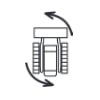 |
Turn Left | Indicates the machine is turning left |
 |
Lift Arm Raise / Bucket Up | Indicates the lift arm is raising or the bucket is being lifted |
 |
Lift Arm Lower / Bucket Down | Indicates the lift arm is lowering or the bucket is being lowered |
 |
Loader Bucket Dump | Indicates the Kubota loader bucket is being dumped |
 |
Loader Bucket Rollback / Tilt | Indicates the loader bucket is being rolled back or tilted |
 |
Loader Bucket Float | Indicates the Kubota loader bucket is in float mode |
 |
Loader Quick Hitch Lock | Indicates the loader quick hitch is locked. Locks the loader bucket or attachment into position quickly |
 |
Loader Bucket Self Leveling | Indicates the loader bucket is self-leveling. Automatically adjusts the loader bucket to maintain a level position |
 |
Ride Control | Indicates that the ride control feature is active, improving ride comfort by damping loader arm movements. |
 |
Quick Attachment Unlock | Indicates that the quick attachment locking mechanism is disengaged / the quick attachment system is unlocked. |
 |
Self Leveling Indicator | Indicates that the self-leveling function of the loader is active, keeping the bucket level as the arms are raised or lowered. |
 |
Tailgate Safety Cover | Shows the tailgate safety cover is engaged. |
 |
Loader Joystick Handle | Indicates the status or position of the loader joystick handle. |
You can find all these dashboard symbols on the following Kubota tractor models:
- Aste Series – A-15, A-17, A-19, A-155, A-175, A-195.
- B Series – B1410, B1550, B1610, B1750, B2150, B2710, B2910, B4200, B5200, B6200, B7100HST, B7100HSD, B7400, B7500, B7800.
- B-01 Series – B2301, B2401, B2601.
- B1 Series – B1121, B1161, B1181, B1241.
- B2 Series – B2201, B2231, B2261, B2311.
- B26 TLB Series – Kubota B26TLB.
- B2x20 Series – B2320, B2620, B2920.
- B30 Series – B1830, B2230, B2530, B2630, B3030, B3030.
- B50 Series – B2050, B2350, B2650, B2650, B3150, B3350.
- B7x10 Series – B7410, B7510, B7610.
- BX Series – BX1500, BX1800, BX1870-1, BX2200, BX2370-1, BX2670-1.
- BX30 Series – BX1830, BX2230.
- BX50 Series – BX1850, BX2350.
- BX60 Series – BX1860, BX2360, BX2660.
- BX70 Series – BX1870, BX2370, BX2670.
- BX80 Series – BX1880, BX2380, BX2680.
- FT Granforce Series – FT21, FT23, FT25, FT28, FT30, FT220, FT240, FT300.
- GB Series – GB13, GB14, GB15, GB16, GB18, GB20, GB110, GB115, GB130, GB135, GB140, GB145, GB150, GB155, GB160, GB170, GB175, GB180, GB200.
- GL Series – GL19, GL21, GL23, GL25, GL26, GL27, GL29, GL32, GL33, GL200, GL201, GL220, GL221, GL240, GL241, GL260, GL261, GL268, GL277, GL280, GL281, GL300, GL301, GL320, GL321, GL337, GL338, GL367, GL368, GL417, GL418, GL467, GL-35, GL-40, GL-43, GL-46, GL-53, GL-350, GL-400, GL-430, GL-470, GL-530, GL-600.
- GM Series – GM49, GM56, GM64, GM73, GM75, GM82, GM90.
- GT Series – GT-3, GT-5, GT-8, GT-19, GT-21, GT-23, GT-26, GT-30.
- Globe Series – M100G, M110G, M115G, M125G, M135G.
- Grand L Series – L2900, L3300, L3600, L4200.
- Grand L10 Series – L3010, L3410, L3710, L4310, L4610.
- Grand X Series – M100GX, M110GX, M126GX, M135GX.
- Grandom Series – M85D, M90, M95D, M100, M105D, M115, M115D, M125, M125D.
- Grandom A Series – M90A, M100A, M110A, M115A, M125A, M135A.
- JB Bullstar Series – JB11, JB13, JB14, JB16, JB18.
- JB Bullstar Extra Series – JB11X, JB13X, JB15X, JB17X, JB19X.
- KB Kingbull Series – KB16, KB18, KB20, KB165, KB185, KB205, KB225.
- KB Kingbull Extra Series – KB17X, KB19X, KB21X, KB23X.
- KL Series – KL21, KL23, KL25, KL27, KL28, KL30, KL31, KL33, KL34, KL36, KL38, KL41, KL43, KL46, KL50, KL210, KL225, KL230, KL245, KL250, KL265, KL270, KL280, KL285, KL300, KL310, KL315, KL330, KL340, KL345, KL360, KL380, KL385, KL410, KL415, KL430, KL460, KL465, KL500, KL505, KL550.
- KL Kingwel 50 Series – KL2450, KL2750, KL2850-PC, KL3150, KL3450, KL3950, KL4350, KL4750, KL5150, KL5550.
- KL Kingwel R Series – KL24R, KL26R-PC, KL27R, KL28R-PC, KL31R, KL34R.
- KL Kingwel Zero Series – KL31Z, KL34Z, KL37Z, KL40Z, KL44Z, KL48Z, KL53Z, KL58Z.
- KT Kingeye Series – KT20, KT22, KT24, KT27, KT30, KT210, KT215, KT230, KT235, KT250, KT255, KT280, KT285, KT300, KT305.
- L01 Series – L2501, L3301, L3901, L4701.
- L02 Series – L2502, L3302, L3902, L4802.
- L30 Series – L3130, L3430, L3830, L4330, L4630, L5030.
- L40 Series – L3240, L3540, L3940, L4240, L4740, L5040, L5240, L5740.
- L50 Series – L2350, L2650, L2950, L3450, L3650.
- L60 Series – L3560, L4060, L4760, L5060, L5460, L6060.
- LX Series – Kubota LX2610, LX3310.
- M Series – M110, M120, M4700, M4900, M5400, M5700, M6800, M8200, M9000.
- M1 Series – M1-46, M1-55, M1-65, M1-75, M1-85, M1-100, M1-115.
- M30 Series – M4030, M4030SU, M5030, M6030, M7030, M8030.
- M4 Series – M4-061, M4-071.
- M4002 Series – M4062, M4072.
- M4003 Series – M4063, M4073.
- M5 Series – Kubota M5-091, M5-111.
- M50 Series – M4950, M5950, M6950, M7950, M8950.
- M5001 Series – M5071N, M5091, M5091N, M5101N, M5111.
- M5002 Series – M5092, M5112.
- M6 Series – M6-101, M6-111, M6-131, M6-141.
- M60 Series – M6060, M7060, M8560, M9960.
- M6002 Series – M6122, M6132, M6142.
- M7 Series – M7.131, M7.151, M7.171.
- M7002 Series – M7132, M7152, M7172.
- M7003 Series – M7133, M7163, M7173.
- M8 Series – Kubota M8-181, M8-201.
- M80 Series – M7580, M8580, M9580.
- MD Series – MD77, MD87, MD97, MD107, MD117.
- MGX III Series – M95GX-III, M105GX-III, M115GX-III, M125GX-III, M135GX-III.
- MGX IV Series – M95GX-IV, M105GX-IV, M115GX-IV, M125GX-IV, M135GX-IV.
- MX Series – MX4700, MX4800, MX5000, MX5000SU, MX5100, MX5200, MX5400, MX5800, MX6000.
- Rexia Series – MR77, MR87, MR97.
- ST Series – ST-25, ST-30, STA-30, STA-35.
- STV Series – STV32, STV36, STV40.
- STW Series – STW34, STW37, STW40.
- Standard L Series – L2500, L2600, L2800, L3000, L3200, L3400, L3800, L4300, L4400, L4600.
- Super SynerZ Series – SMZ76, SMZ85, SMZ95, SMZ805, SMZ875, SMZ955.
- SynerZ Series – Kubota MZ50, MZ55, MZ60, MZ65, MZ70, MZ75, MZ505, MZ555, MZ605, MZ655, MZ705, MZ755.
Color of Kubota Warning Lights
Kubota warning lights typically come in various colors, each indicating a different level of severity or type of alert. Here’s a general guide to the colors used for Kubota warning lights:
- Red Warning Lights: These lights indicate critical issues that require immediate attention or could potentially lead to serious damage or safety hazards if ignored.
- Amber or Yellow Warning Lights: These lights signify warnings or alerts that are less severe than red warnings but still require prompt attention to prevent potential problems or malfunctions.
- Green Warning Lights: Green lights often indicate normal or operational statuses, such as systems that are engaged or functioning properly.
- White or Blue Warning Lights: Blue lights may indicate informational or advisory messages rather than immediate warnings. They could signal the activation of specific systems or provide status updates. White lights are less common but may be used to indicate specific conditions or statuses, depending on the equipment and manufacturer’s design.
By understanding the colors associated with Kubota warning lights, operators can quickly assess the urgency of any alerts and take appropriate action to address them, ensuring the safe and efficient operation of their Kubota equipment.
How to Reset Kubota Warning Lights?
Resetting Kubota warning lights typically involves addressing the underlying issue that triggered the warning in the first place. Here’s a general guide on how to reset Kubota warning lights:
- Address the Issue: First, identify the cause of the warning light (error code). Refer to the operator’s manual or diagnostic error codes to understand the specific problem that triggered the warning.
- Fix the Problem: Once you’ve identified the issue, take the necessary steps to address it. This could involve repairing or replacing faulty components, replenishing fluids, or performing maintenance procedures.
- Turn Off the Engine: Shut off the engine and wait for a few seconds to ensure that all systems reset properly.
- Restart the Engine: Start the engine again and monitor the warning lights. If the issue has been successfully resolved, the warning light should turn off. If it persists, there may be an ongoing issue that requires further attention.
If you’re unable to resolve the issue on your own or if the warning light continues to illuminate after troubleshooting, it’s recommended to seek assistance from a qualified Kubota technician. They can diagnose the problem more thoroughly using diagnostic tools and equipment.
It’s important to address warning lights promptly to prevent potential damage to your Kubota equipment and ensure safe operation. Regular maintenance and inspections can also help prevent warning lights from appearing in the first place.

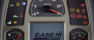
Hello, I am working on a Kubota SCL 1000. Recently got it back from a rental client, and it has a #7 Master System Warning Indicator light. I am just wondering what this code means. I appreciate your time. Thank you, Colin
The “Master System Warning Indicator” on a Kubota tractor dashboard is a general warning light that alerts the operator to potential issues with the tractor’s systems. When this indicator is illuminated, it means there is a problem or fault within one or more of the tractor’s key systems, such as: Engine, Transmission, Hydraulics, Electrical system. The Master System Warning light typically appears when a sensor detects an abnormal condition or malfunction. It may be accompanied by an error code or additional warning lights that help pinpoint the specific issue.